BENEFITS
Welding
Due to low carbon content, age hardening, and the availability of NAK weld rod, hardness is lowered in the heat-affected zone during the welding process. NAK55 can be re-aged to 40 HRc with no distortion or stress put into the mold. Polish, texture and wear in the weld are indistinguishable from adjoining “parent steel” on the finished product.
Machining
Machines up to 50% faster than P20 to a superior surface with negligible dimensional change. Positive rake cutters with concave, chip breaking inserts work best, and last up to twice as long as with P20 mold steels.
EDM
The soft recast layer (approximately 32 HRc) is much thinner and is easier to remove than steels with a recast layer that is equivalent to their “as quenched” hardness. With NAK55, no post-EDM stress relieving is ever needed.
Stability
Age hardening eliminates the stresses inherent in quenched and tempered steels. NAK55 is dimensionally stable and predictable over many years of heating and cooling cycles.
Surface Enhancements
VAR processing with uniform grain structure facilitates superior nickel, chrome, titanium, and other coatings. Unique chemistry responds extremely well to ion-nitriding.
Texturing and Polishing
Exceptionally clean steel with uniform grain structure polishes beautifully allowing superior texturing and photo etching.
Wear

The uniform, refined grain structure of NAK55
Higher hardness ensures molds have a longer life than those made from P20, particularly in gate, runner, and parting line areas.
MECHANICAL PROPERTIES
Tensile Strength 182,000 psi
Yield Strength (.2% offset) 146,500 psi
Reduction of Area 39.8%
Elongation in 2″(longitudinal) 15.6%
Modulus of Elasticity (room temp.) 30.00 x 10⁶psi
Charpy V-notch Impact Strength:
Longitudinal 7.2 ft./lb.
Transverse 5.6 ft./lb.
Hardness 40 HRc
PHYSICAL PROPERTIES
Compressive Strength
NAK55 possesses excellent resistance to surface deformation by compressive force. Its resistance to surface deformation equals that of H-13 steel at like hardness.
Stability
NAK55 is not quenched to achieve hardness. Therefore, it does not have the stresses inherent in quenched and tempered steels. NAK55 never needs stress relieving due to heavy machining because of uniform hardness throughout! It has excellent dimensional stability during mold construction and while in service. Even after long mold runs, cool-down, and subsequent re-heating, the material maintains dimensional stability.
Operating Temperature Ranges
NAK55 is a precipitation-hardening steel. The formation of the precipitates occurs at a temperature range between 932° and 968°F. Exposure to temperatures below the original precipitation hardening temperature does not affect the grain structure of the steel. Therefore, even molds in service at high operating temperatures maintain dimensional stability. Similarly, nitriding or Physical Vapor Deposition (PVD) treatments done below the precipitation hardening temperature range do not cause distortion. This is a tremendous advantage over typical mold steels that have been tempered at low temperatures to maintain hardness.
Hardness
The precipitates, which account for the steel’s hardness, begin to grow in size if the original hardening temperature range for NAK55 (932°–950°F) is exceeded for an extended period of time. This results in a loss of hardness and toughness, and accompanying dimensional change. Re-solution heat-treating and subsequent precipitation hardening can recover hardness and toughness, but dimensional changes will have occurred.
Wear Properties
NAK55 is a low carbon steel that acquires hardness by precipitation hardening. Very small carbide structures and precipitates are formed during the hardening process. Care is required when NAK55 steel slides against itself in molding situations. The use of dissimilar metals, with a 10 HRc point difference on the mating surfaces, is advisable in slide situations. Alternatively, you may change the hardness of the surface of similar metals by plating, nitriding, or applying other types of coatings.
Shut-Off Tolerances
The tolerance between mating surfaces on angle shut-offs is very important, and proper setting of the mold is required. The recommended tolerance at molding temperature is .0008″ per side for ABS, Polypropylene, Polyethylene, etc. A .0004″(.01mm) per side clearance is required for Polyacetals or nylons, due to their lesser viscosity.
Ejector Pin Tolerances
Dia. of Ejector Pin | Recommended Clearance |
Note: All clearance values are at molding temperature.
Sharp Corners
Sharp or square corners serve as focal points for concentrating stresses that build up in molds and dies during operating conditions. A .100″– .120″ radius to all corners is recommended, especially large box-type molds. To avoid these stresses, the thickness of the material backing up a sharp corner should be increased by 50% when compared with softer steels.
Thin Sections
Due to the toughness limitations of NAK55, it is suggested that other types of steel be inserted at thin rising sections (4-to-1 ratio or more) and that a radius be put on the base of rising sections from the initial design stages.
Cavity Depth
Cavity depth should be limited to no more than 50 – 55% of the block thickness in high-pressure injection molds.
Cooling/Heater Water Lines
Do not locate cooling or heater lines directly below the corner of a mold cavity. The ideal location for heating or cooling lines is three (3) times the hole diameter from the molding surface. 1.5 times the hole diameter from the molding surface is the minimum. Example: a 1/4″diameter waterline should be at least 3/8″ away from mold surface and preferably 3/4″. The distance between lines should be five (5) times the line diameter minimum.
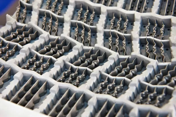
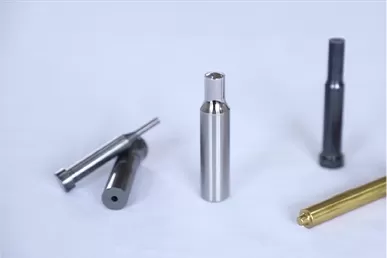
NAK 55 mold inserts. Photo courtesy of Tooling Express, Inc.
Coefficient of Thermal Expansion (x 10-6in/in/F°)
- 68°F to 212°F 6.3
- 68°F to 392°F 7.0
- 68°F to 572°F 7.5
Coefficient of Thermal Conductivity (BTU/ft•hr•F°)
- At 200°F 23.9
- At 400°F 24.4
Magnetic Properties
- Maximum Magnetic Permeability 380
- Saturated Magnetism (Gauss) 16,350
- Residual Magnetism (Gauss) 8,500
- Coercive Force (Oersted) 14.0
CHEMICAL COMPOSITION
- Carbon 0.15%
- Copper 1.00%
- Sulfur 0.10%
- Nickel 3.00%
- Silicon 0.30%
- Aluminum 1.00%
- Manganese 1.50%
Processing Guidelines
The optimum cutting conditions for NAK55 vary by machine tools. Cutting tools incorporating the recommended geometries will produce superb finish machined surfaces, often completely eliminating grinding. NAK55 does not work harden.
- Milling
High-speed steel cutters give excellent results and very smooth machined surfaces. The best results are obtained with cutter geometries incorporating a positive rake angle of 15°–20° and a relief angle of less than 10°.Carbide cutting tools (P40 grade) will yield excellent results if the effective, positive rake angle of the insert and holder is approximately 8°-15°, and the relief angle is less than 10°. When a negative rake carbide is used, inserting grades with greater toughness than P40 gives better results. In general, a positive rake configuration is superior to a negative rake configuration for milling NAK55.Note: It is important that the inserts have a concave face with a sharp chip breaking edge. TiAlN coatings work well.
- Grinding
NAK55 grinds easily. It is recommended that it be ground wet. - Drilling
NAK55 drills easily. The cutting speed should be lowered as the drill diameter increases. A smaller than standard twist angle and shorter length will reduce the danger of broken tools. Peck cycles are recommended, as NAK55 is a chip packing material. - Tapping
NAK55 is a 40 HRc steel. The following is recommended to facilitate tapping:
- Use a new, sharp, premium grade of tap, TiN coated and spiral pointed.
- Use a tapping oil or highly chlorinated sulfurized oil. A mixture of 50% kerosene and 50% cutting oil also works well.
- EDM
Copper or graphite electrodes are suitable, or the steel may be used as an electrode when burning mating halves together to achieve a fit.The recast layer for NAK55 is soft (approximately 32 HRc). Other low alloy grades such as P20, or more highly alloyed steels such as S7 and H13, have recast layers equivalent to their high, as-quenched hardness. Because the EDM white layer must be removed, the subsequent stoning or grinding of NAK55 is much easier than with other steels.NAK55 may develop a striped pattern with a low amperage finishing burn.
- Polishing
NAK55 is a Vacuum-Arc Remelted steel of exceptional cleanliness and as such, it polishes beautifully.Normal polishing techniques will yield excellent results. All stoning operations should be done with reciprocating tools.Note: No rotary stoning.
NAK55 steel contains uniformly dispersed manganese sulfides. These sulfides reduce friction between the steel and the stones and actually improve polishability. However, if a circular motion is used, the sulfides can be lifted up from the surface creating the appearance of pits. Therefore, it is important to use a reciprocating stoning technique and light pressure during buffing.
Due to the sulfide content of NAK55, do not exceed 3000 grit Diamond Compound.
- Texturing
NAK55 is an ideal steel for photo etching or texturing. Vacuum-Arc Remelted processing employs a continuous ingot casting procedure that nearly eliminates chemical segregation of the alloying elements. This results in a clean, homogenous steel.The low carbon content of NAK55 is also advantageous, since carbon is a potent alloying element and a major contributor to chemical segregation.The uniform hardness of NAK55 assures even and uniformly textured patterns regardless of workpiece size or depth of cavity. Furthermore, the ability to easily restore a uniform hardness to welded areas is a tremendous advantage for texturing in comparison to other steels. - Nitriding
NAK55 contains 1% aluminum and responds very well to nitriding. There are many forms of nitriding and each has advantages. However, for molding die applications, ion-nitriding, in particular, is very suitable for NAK55. When employing standard gas nitriding do not exceed 950°F.The ion-nitriding process is done in a controlled atmosphere. It is clean, with minimal distortion, and can be done at temperatures that do not damage NAK55.Nitriding increases wear resistance and creates a hard surface ideal for slides or dies that mold abrasive or mineral-filled thermoplastics. The nitrided surface has a hardness over 60 HRc, improved corrosion resistance, and can be polished to a finer finish than possible at base metal hardness.


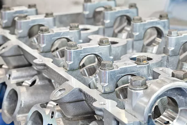
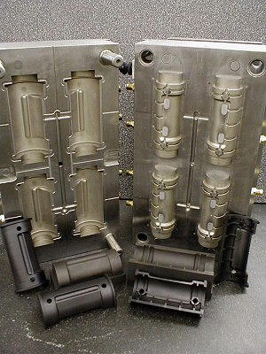
Design change capability (5th engineering change on this tool)
Welding Guidelines
General
- The die or mold should be free of all oil, rust, scale residue, or any other potential contaminants before attempting to weld.
- All cracks and surface treatments should be completely removed before attempting to weld.
- Sharp corners should be rounded to a minimum radius of .120″.
- To repair a crack, remove sufficient stock to eliminate the crack and ensure only sound material remains. Dress the corners where stock was removed to eliminate any square corners by rounding to a minimum radius of .120″.
Preheating
Prior to making a welding repair, preheat the piece to be repaired by slowly heating in a furnace or with a gas burner to between 600° and 750°F. Heating from the bottom is recommended if a gas burner is used. Uniform temperatures within the recommended range should be maintained during the entire period of time required to complete the repair. Ideally, the entire mold should be heated in a furnace to achieve uniform temperatures. This is easy to do for small molds, but may not be practical, or possible, for large molds. Localized preheating is the only option for large molds, and attention must be paid to the following:- Preheating temperature must be achieved to at least 2″ away in all directions from area to be welded.
- Use an oxygen-propane gas burner with a low flame temperature. Heat the mold carefully and gradually, maintaining a distance of 18″ between the flame and the mold surface.
- Apply a temperature choke or a surface contact thermometer to accurately measure the preheating temperature.
- Re-heat as necessary during welding to maintain the above 600°F range.
Technique
- Use DC normal polarity
- Use lowest possible amperage for the job
- Use backhand welding – weld away
- Use smallest diameter rod possible
- Weld small beads
- Peen weld as necessary
- Upon completion of welding, proceed immediately to post-weld heating procedure
Post-Weld Heating
It is imperative that the following procedure be carefully followed to ensure the welded section is completely restored to a uniform hardness: The weld-repaired piece should be heated to between 860°F-940°F and held at this range for a minimum of one (1) hour to re-age. This re-aging process should be conducted immediately after welding. Heating with a furnace is highly recommended, however a gas burner may be used as a last resort. If a gas burner is used, heating from the bottom is recommended, however the entire welded area, and as much as 2″ surrounding the weld, must be kept in the post heat temperature range for a minimum of one (1) hour. Cool slowly to room temperature.Note: Post-weld heating should be performed after every three layers of weld buildup in order to alleviate welding stress and avoid over-aging of adjacent parent metal.
Conditions
Rod diameter .0470″ .0630″ .0946″ | Electrode diameter .0470″ .0630″ .0946″ | Current/Amps 40~70 70~150 150~250 |
Technical Center
International Mold Steel specializes in pre-hardened mold and tool steels that are considered to be the finest available in the market place today. Because of their unique and homogenous make-up, deviation in hardness or hard spots is a thing of the past. When machining these materials it will become immediately apparent that much faster metal removal rates can be achieved.
Material Removal Rates
Consider this: material removal rate during this time span in approximately 300 pounds of steel. It showed that we could remove a lot of steel with moderate surface feet but a heavy chip load. Once again, the clean make-up of the material made this possible.
To Calculate Surface Feed
Surface speed is usually given in feet per minute. It is the distance (in feet) that the outermost cutting edge of a rotating tool (circumference) covers in the span of 1-minute.
To understand how this translates into spindle speed, or revolutions per minute (rpm) that the cutting tool is revolving, review this example:
Example:
Surface feet 400 feet per minute Diameter of cutting tool is 4 inches. Revolutions per minute (rpm) if cutting tool is ____
Equation:
C = Surface feet per minute (feet) D = Diameter of cutting tool (inches) R = Revolutions per minute of cutting tool (rpm)
R = (C x 12) = (400 x 12) = 4800 = 382 rpm
(D x Pi) (4 in. x 3.14) 12.56
If you need to know surface feet per minute and the cutter diameter and spindle speed is known, you will have this equation:
C = | Pi x D x R __________ 12 | = | 3.14 x 4 x 382 __________ 12 | = 400 sf. |
To Calculate Chip Load
Chip load is the amount of materials (in .001 inches) that each cutting flute or cutting insert of a rotating tool removes.
Chip load is calculated by dividing the distance of the table travel or feed per minute in inches by the spindle speed of the machine. This will give you the distance the cutter traveled in one revolution. This number is then divided by the number of cutting flutes or inserts.
Example:
Spindle speed is 450 rpm. Table travel or feed rate is 60 inches per minute. Number of flutes or cutting inserts is 6.Equation:
R = Spindle speed (rpm)
I = Number of cutting flutes or inserts
S = Distance of feed rate or table travel in inches.
C = Chip load
C = | ( | S ___ | ) ( | 60 ____ | ) | = | .13333 __________ 6 | = .0222 |
I |
To Calculate Feed Rate
S = C x I x R =
S = .0222 x 6 x 450
To find rpm of spindle or R with chip load and feed rate known:
R = | S _____ I x C | = | 60 __________ 6 x .0222 | = 450 rpm |