Savings Calculator
Benefits
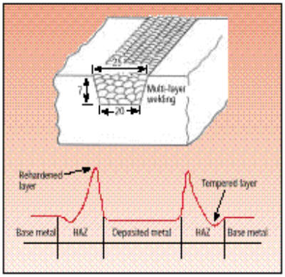
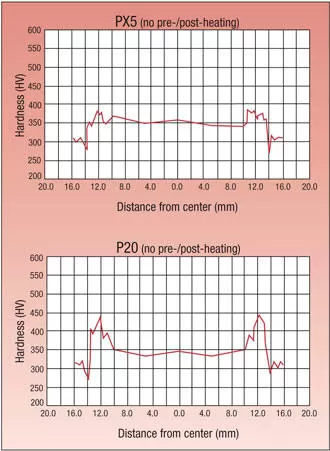
Welding
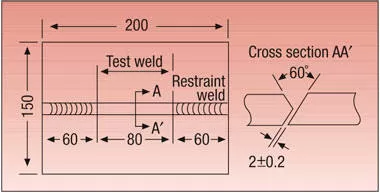
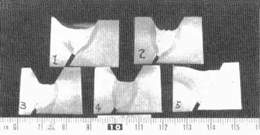
Superior mold quality after welding. Low hardness of heat affected zone eases post-weld cutting and grinding operations and minimizes mold distortion, etch unevenness, and differences in luster upon mirror finishing. Unique composition eliminates weld cracking.
Machining
Rough machines up to 50% faster than P20 (30% overall) to a superior surface with negligible dimensional change. Use of PX5 assures the longest cutting tool life of any 30 HRc, P20-type material. Consistent hardness and microstructure allow dependable, unattended machining.
EDM
EDM surface hardness is about 70% of that produced by typical P20-type steels. Post-EDM grinding and polishing operations are simpler and more consistent, and problems
such as surface layer cracking or peeling are reduced.
Stability
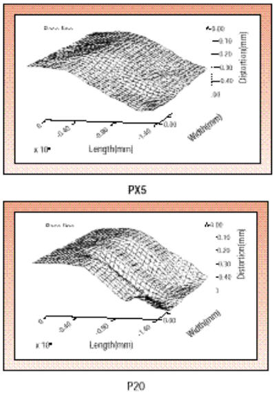
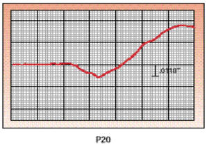
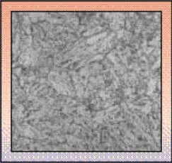
Uniform hardness and refined grain structure assure the highest level of dimensional stability (after machining) of any P20-type mold steel.
Surface Enhancements
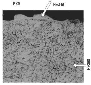
Can be ion-nitrided to produce a surface hardness over 60 HRc with negligible distortion or dimensional change.
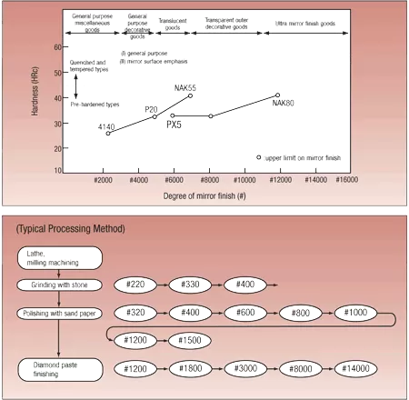
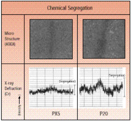
Texturing and Polishing
Uniform microstructure and hardness give PX5 the best surface-finish characteristics of any P20-type material. Low chemical segregation eliminates the occurrence of photo etch unevenness.
Toughness
Exceptional toughness reduces cracking problems in molds.
Mechanical Properties
- Isotropy and Uniform Strength PX5’s strength is approximately the same at the center and surface of the material, and that isotropy (T/L) is at least 0.05.
Tensile Properties
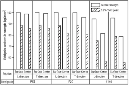
When designing deep cavities in molds, PX5’s consistent toughness assures the mold center will have sufficient strength, and cracking problems are dramatically reduced.
Toughness
General Design Guidelines
- Compressive Strength
Uniform hardness (approximately 32 HRc) from surface to core assures that strength and hardness at the mold center are the same as at the surface. Exceptional toughness reduces cracking problems while increasing flexibility in mold design.
- Stability PX5 is substantially more stable than common P20-type steels. Since it has a unique heat treating process, it does not have the stresses inherent in typical quenched and tempered steels. PX5 never needs stress relieving, even after heavy machining. It has excellent dimensional stability and consistency during the machining process, and during the heating and cooling cycles of injection or compression molding.